it contains an ID but the ID is duplicated (i.e. someone else has reported the same ID earlier)
the board is a counterfeit.
Users are urged to refrain from purchasing counterfeit DSO138 kits to avoid helping a thief. If you unintentionally
purchased counterfeit DSO138 you are strongly encouraged to report the seller to eBay, Amazon, or AliExpress, or post it to public forums.
And you have the right to protect yourself by requesting a full refund to your seller.
In order to protect your rights it is strongly suggested that buyers contact seller before placing order to make sure his/her DSO138 kits contain
the ID. All JYE Tech DSO138 boards have gone through strict testing procedure which counterfeit boards do not have. Please see this [Video: Board Test in Production ]
List of sellers who were reported selling counterfeit DSO138 kits
Recommended DSO138 Kit Sellers
What's New
[2015-01-05] New firmware (113-13801-060) released with following improvements:
Auto-center trigger level to the middle of signal amplitude when trigger level is focused and OK button is held down for 2 seconds. This is useful for quickly stabilize waveform display. (Thank Gabriel S. for the suggestion!)
Auto-center horizontal position when horizontal position is focused and OK button is held down for 2 seconds. (Thank Gabriel S. for the suggestion!)
Restore factory default settings when "+" and "-" buttons are held down simultaneously for 2 seconds.
Improved frequency measurement by using average voltage level (instead of true 0V level which was used in previous versions) as cycle counting reference.
Fixed a bug in trigger level readout error. In previous versions trigger level readout displayed wrong value after VPos alignment was performed.
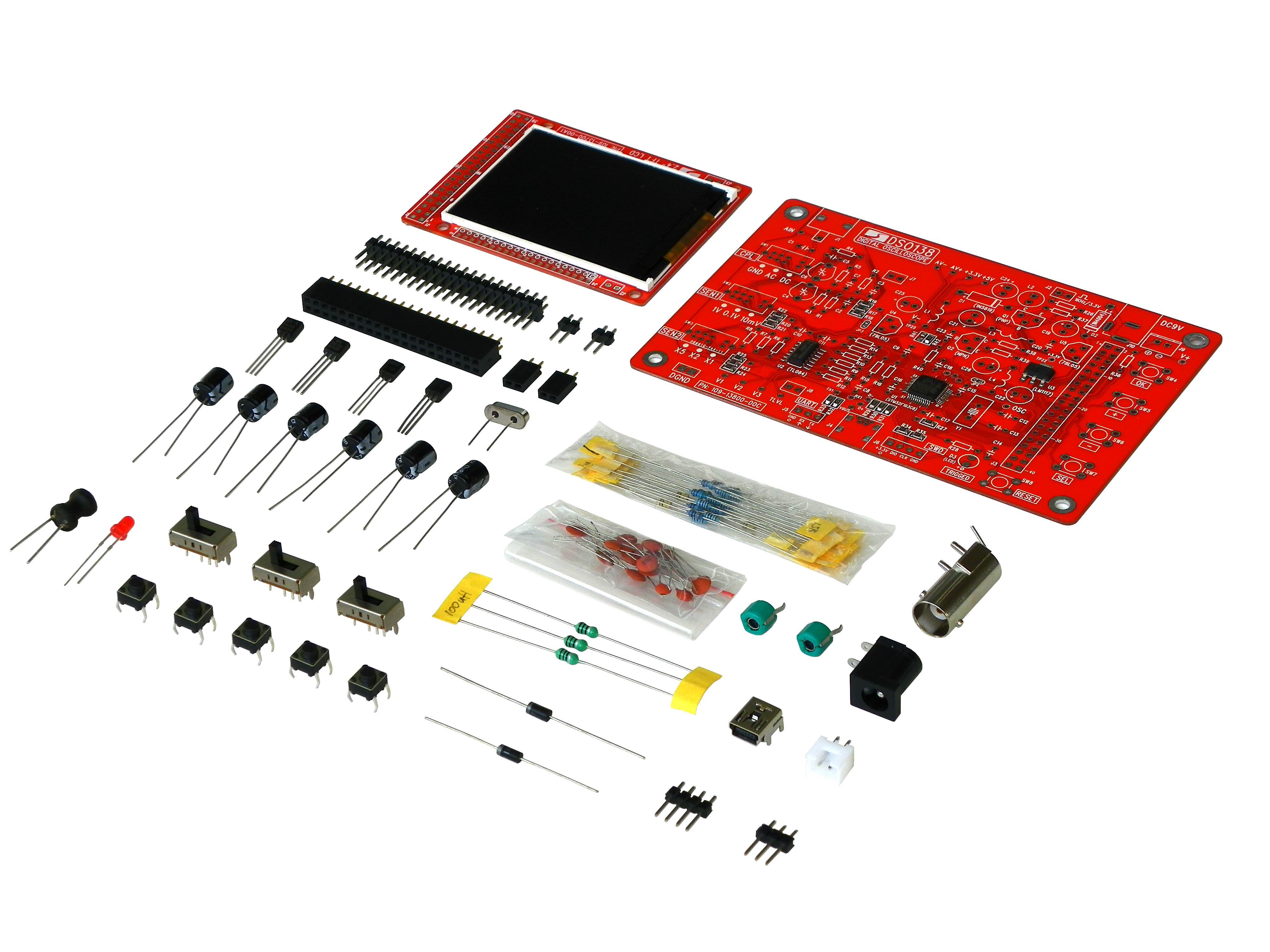
DSO138 DIY Kit
DSO138 was designed as a training oscilloscope kit. It contains only the basical oscilloscope functions with no fancy features. Simplicity in structure and easiness
in assembly/operation are among the main targets of the design. For these purpose DSO138 uses mostly through-hole parts. The heart of DSO138 is a Cortex-M3
ARM processor (STM32F103C8) from ST. It uses 2.4-inch TFT LCD (320 X 240 dotmatrix, 262K colors) as its display element and displays nice and clear waveforms.
Detailed assembly instructions are provided in combination with troubleshooting guide and schematc. Source codes are also available to allow user to add their own
features.
DSO138 kits are sold in two configurations. One is with all SMD parts pre-soldered (PN: 13803K, replacing 13801K). The other is with only the main IC (the MCU) pre-soldered
(PN: 13804K, replacing 13802K). The latter serves also as a SMD soldering training kit. For both configurations the MCU has been pre-programmed and no re-programming required.
13803K and 13804K are newly released improved models with following upgradings:
Significantly lowered noises. Comparing:
[NEW] vs
[OLD] in measuring the built-in test signal.
Waveform can be saved to and recalled from non-volatile memory.
Enhencement in Test Mode with auto short-circuit detection capability.
Supports two types of TFT controllers (ILI9341 and ILI9325/9328).
DSO138 is partially open-sourced. This opens the possibility for users to add different features or develop new applications on the hardware.
Major features of DSO138:
Analog bandwidth: 0 - 200KHz
Sampling rate: 1Msps max
Sensitivity: 10mV/Div - 5V/Div
Sensitivity error: < 5%
Vertical resolution: 12-bit
Timebase: 10us/Div - 500s/Div
Record length: 1024 points
Built-in 1KHz/3.3V test signal
Waveform frozen (HOLD) function available
Save/recall waveform
Important Notes
It is assumed that users have adaquate soldering skills and troubleshooting skills to assemble the DSO138 kits. It is not guaranteed that you will end up with a working device.
But we make as much efforts as we can to approach that goal.
Before packing each mainboard has been tested to ensure no short or open on MCU soldering (see
[Video] Board Test in Production ).
Each LCD board is also tested to verify soldering is good and display is functional. However, all the rest components are
provided with good quality at our best knowledge. They are not tested since that is not practical in production.
For 13804K kit SMD component soldering skills are required. SMD parts should be installed before all other through-hole parts. It is strongly suggested to search the internet to get knowledge of SMD
soldering if you are not sure of and want to purchase the 13804K kit.
Ordering Info
Sku Number
Contents
13803K
One DSO138 kit with all SMD parts pre-soldered
One BNC-clip cable
Users Manual (English)
13804K
One DSO138 kit with only the major IC chip (the MCU) pre-soldered
One BNC-clip cable
Users Manual (English)
Note 1:
A 9V DC power supply is required to run DSO138. Power supply is not included in the kit. It is recommended
to use the 5V-to-9V Step-up Converter JYE140 to power DSO138 by battery or USB.
[see Photo: DSO138 working with JYE140]
Note 2:
The only hardware diffference between 13803K/04K and 13801K/02K is the value of R11. For 13803K/04K R11 uses 150 ohm. For 13801K/02K it is 1.5K.
Note 3:
All firmware versions earlier than 113-13801-050 (including the source code package) can only be used with 13801K/02K. 113-13801-050 is for 13803K/04K.
Note 4:
For models 13803K and 13804K to use the open-source firmware users need to change R11 to 1.5K (this converts 13803K/04K to 13801K/02K).
Note 5:
Models 13801K and 13802K were discontinued. Shipment of 13801K/02K were stopped as of July 1, 2015
Important:
For model 13804K it is strongly recommended to install all SMD parts first and then the through-hole parts. Otherwise, installed through-hole parts will make SMD parts
soldering difficult.
Product Documents and firmwares:
Specification
Vertical
Number of Channel: 1
Analog Bandwidth: 0 - 200KHz
Sensitivity: 10mV/Div - 5V/Div
Sensitivity error: < 5%
Resolution: 12-bit
Input Impedance: 1M ohm
Maximum Input voltage: 50Vpk
Coupling: DC, AC, GND
Horizontal
Max Real-time Sampling Rate: 1Msps
Timebase: 10us/Div - 500s/Div
Record Length: 1024
Trigger
Trigger Modes: Auto, Normal, Single
Trigger Types: Rising/falling edge
Trigger Position: 1/2 of buffer size fixed
Display
2.4-inch color TFT LCD with 320 x 240 resolution
Power Supply
9V DC (8 - 12V acceptable)
Supply Current: 120mA
Physical
Dimension: 117mm X 76mm X 15mm
Weight: 70 gram (not including cables)